
Types of Architectural Drawings: 7 Key Examples
- Jun 26, 2025
- 14 min read
Updated: Sep 23, 2025
Building or renovating a home is a significant undertaking, and it all begins with a clear, detailed plan. Architectural drawings are the universal language that translates your vision into a buildable reality, ensuring everyone from your general contractor to your interior designer is working from the same script. But faced with a thick set of documents filled with lines, symbols, and notes, it's easy to feel overwhelmed. Understanding the different types of architectural drawings is the first step toward building with confidence and avoiding costly misinterpretations.
This comprehensive guide will demystify the essential drawings that form a complete set of construction documents. We will explore the specific purpose of each one, from foundational floor plans and exterior elevations to complex section views and detailed construction assemblies. By learning how to read and interpret these plans, you can effectively communicate with your project team, make informed decisions, and ensure the final structure perfectly matches your initial vision. Whether you're building a custom home, planning an addition, or simply want to better understand the design process, this breakdown will equip you with the necessary knowledge to navigate your project like a seasoned professional.
1. Floor Plans
Among the many types of architectural drawings, the floor plan is arguably the most fundamental and recognizable. It presents a top-down, two-dimensional view of a building, imagined as if a horizontal slice was cut through it at about four feet above the floor. This perspective reveals the home’s foundational layout, including the size and arrangement of rooms, the thickness of walls, and the precise locations of doors and windows.
Floor plans are the cornerstone of any residential design project. They serve as the primary reference document that illustrates spatial relationships, circulation patterns, and the overall functionality of a home. Before any other drawing can be developed, the floor plan must be perfected, as it dictates the core living experience and the structural grid for the rest of the building.
Purpose and Implementation
The primary purpose of a floor plan is to communicate the design intent for a building's interior space. For a new custom home, this drawing is used to:
Validate the Design: Homeowners can visualize how they will move through and live in the space, ensuring the layout meets their family’s lifestyle needs.
Guide Construction: Contractors and tradespeople rely on detailed floor plans for the accurate placement of walls, plumbing fixtures, cabinetry, and electrical outlets.
Obtain Permits: Building departments require clear, dimensioned floor plans to verify that the design complies with local building codes and zoning regulations.
This quick reference summary highlights the essential components and benefits of a well-drafted floor plan.
The infographic confirms that floor plans are essential for visualizing layouts and securing permits, commonly drawn at scales like 1/4" = 1'-0" for clarity. Understanding these elements is crucial for anyone new to the home-building process. For those unfamiliar with the symbols and notations, learning how to interpret these drawings is a valuable first step. You can gain a deeper understanding by exploring a quick guide on how to read floor plans and blueprints on rbahomeplans.com.
Best Practices for Floor Plans
To ensure maximum clarity and utility, floor plans must be executed with precision.
Pro Tip: When reviewing a floor plan, mentally "walk" through the space. Imagine carrying groceries from the garage to the kitchen or moving from the master bedroom to the laundry room. This exercise often reveals awkward pathways or inconvenient layouts that aren't apparent on paper.
Key considerations include maintaining a consistent scale throughout the drawing, typically 1/4" = 1'-0" for residential projects. Using standard architectural symbols for doors, windows, and fixtures prevents confusion, while clear dimension strings provide contractors with exact measurements for construction.
2. Elevations
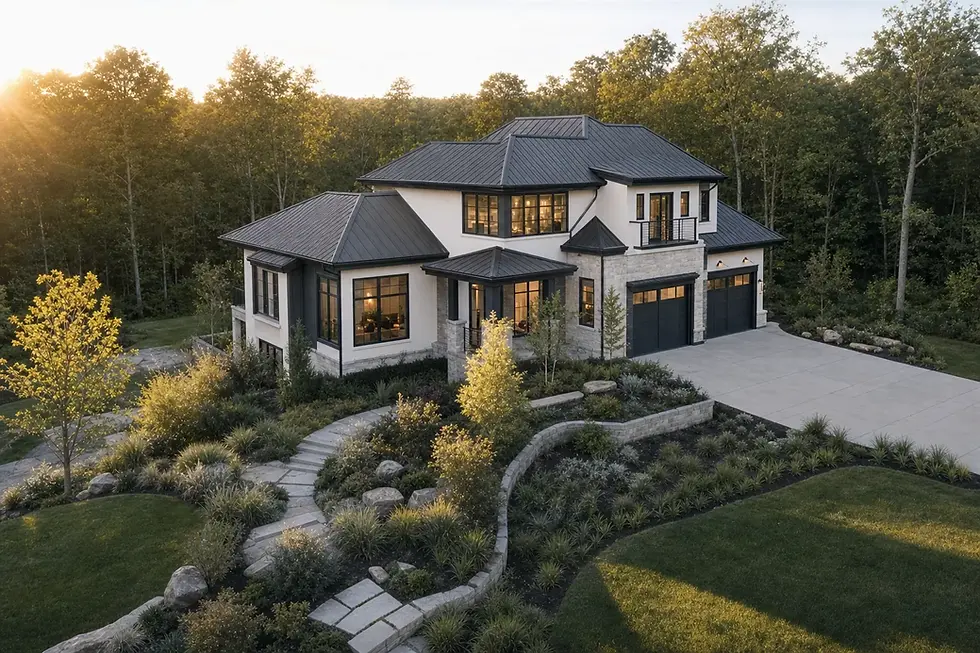
While floor plans map out a building’s horizontal layout, elevations are the types of architectural drawings that depict its vertical exterior surfaces. These drawings offer a flat, two-dimensional, straight-on view of each facade (front, rear, and sides) without any perspective distortion. This orthographic projection is essential for communicating the building's aesthetic character, material finishes, and the vertical relationships between elements like windows, doors, and rooflines.
Elevations are the primary tool for defining a home's external appearance and style. They are indispensable for visualizing how the finished structure will look from the outside and serve as a critical guide for construction, ensuring the design intent is realized accurately. From the modern, fluid facades of Zaha Hadid to the classical symmetry seen in traditional civic buildings, elevations bring the architectural vision to life.
Purpose and Implementation
The main purpose of an elevation drawing is to articulate the exterior design and specify construction details for the building's shell. For a new custom home, this drawing is used to:
Define Aesthetics: Homeowners and architects use elevations to finalize material choices like siding, brick, or stone, as well as window styles and trim details.
Guide Exterior Construction: Builders rely on elevations for the precise placement of windows, doors, roof pitches, and decorative elements. They also specify finished grade levels around the foundation.
Secure Approvals: Architectural review boards and homeowners' associations (HOAs) require detailed elevations to ensure the proposed design complies with community standards and aesthetic guidelines.
This summary shows how elevations bridge the gap between abstract plans and the tangible, visible reality of a home's exterior.
Best Practices for Elevations
To be effective, an elevation drawing must be clear, detailed, and perfectly coordinated with other drawings in the set.
Pro Tip: Clearly label each elevation drawing according to the direction it faces (e.g., "North Elevation," "Front Elevation"). This simple practice prevents costly mix-ups during construction, especially on complex or irregularly shaped lots.
Key best practices include using different line weights or hatch patterns to clearly distinguish between different materials, such as stone veneer versus stucco. It's also crucial to coordinate all vertical heights with the corresponding floor plans and section drawings to ensure accuracy. Including key landscape features like trees or retaining walls can also provide valuable context for how the home will sit on its site.
3. Sections
While floor plans slice a building horizontally, sections are another of the essential types of architectural drawings that do so vertically. A section drawing illustrates a building as if it were cut open by a vertical plane, revealing the composition of its interior spaces, structural framework, and vertical circulation elements like stairs or elevators. This view is critical for understanding the three-dimensional experience and volume of a space.
Sections are fundamental for communicating the vertical relationships within a design. They move beyond the simple layout to show how different levels connect, the true height of ceilings, and the impact of features like cathedral ceilings or split-level floors. For architects like Louis Kahn and Tadao Ando, the section was a primary tool for exploring light, volume, and human experience, proving its power beyond simple technical documentation.
Purpose and Implementation
The main purpose of a section drawing is to clarify the vertical aspects of a building that a floor plan cannot show. In a custom home project, sections are used to:
Visualize Volume and Height: Homeowners can grasp the scale of interior spaces, from a grand two-story great room to more intimate, lower-ceilinged nooks.
Detail Structural Systems: Sections reveal how the roof, floors, and foundations connect, providing crucial information for engineers and contractors.
Resolve Complex Junctions: They show how different materials and building components meet, ensuring weatherproofing and structural integrity at key points like the roof eaves or foundation walls.
This quick reference summary highlights how sections bridge the gap between two-dimensional plans and the three-dimensional reality of the built structure.
Best Practices for Sections
To be effective, section drawings must be carefully planned and clearly executed. The location of the "cut" is paramount to its usefulness.
Pro Tip: When choosing where to cut a section, always slice through the most significant vertical elements. This includes stairwells, double-height spaces, complex roof structures, or areas with significant changes in floor level to reveal the most critical design information.
Key considerations include coordinating section cut lines on the floor plans so it's clear where the view originates. Using distinctive hatching or poche for solid materials like concrete or wood helps differentiate between solid mass and empty space. Lastly, including human figures for scale provides an immediate and intuitive understanding of the size of the rooms.
4. Site Plans
While floor plans focus inward, another of the essential types of architectural drawings, the site plan, looks outward. It provides a comprehensive, bird's-eye view of the entire property, showing how the building relates to its surrounding environment. This drawing illustrates the building's footprint, property lines, setbacks, driveways, walkways, landscaping, and topographical features like slopes and drainage.
Site plans are crucial for understanding the project in its broader context. They bridge the gap between the architectural design and the land it occupies, ensuring the home is thoughtfully integrated into its lot. From zoning compliance to planning outdoor living spaces, the site plan governs how the building interacts with the world outside its walls.
Purpose and Implementation
The primary purpose of a site plan is to map out the relationship between a building and its property. For a new custom home, this drawing is critical for:
Ensuring Zoning Compliance: Site plans demonstrate that the proposed construction adheres to local regulations for setbacks, lot coverage, and height restrictions.
Planning Site Work: Contractors use it to guide excavation, grading, and the installation of utilities like water, sewer, and electrical lines.
Designing Outdoor Spaces: It allows homeowners and landscape architects to visualize and plan for gardens, patios, pools, and other external features.
This drawing is foundational for obtaining permits and coordinating the efforts of various professionals, including civil engineers and landscape architects.
Best Practices for Site Plans
A clear and accurate site plan prevents costly mistakes and ensures a smooth construction process.
Pro Tip: Always verify the site plan against a recent property survey. Relying on old or inaccurate surveys can lead to major issues, such as building over a property line or conflicting with an unknown utility easement. This is a key step in evaluating a lot, which is one of the crucial factors when selecting a plan for your new home.
Key considerations include adding a north arrow and a clear scale to orient the viewer and provide accurate measurements. Using standardized symbols for landscape elements, utilities, and paving materials ensures universal understanding. It's also vital to differentiate between existing conditions and proposed changes, often by using different line weights or styles to avoid confusion during construction.
5. Construction Details
While floor plans and elevations provide the big picture, construction details zoom in on the critical junctions where a building’s components meet. Among the types of architectural drawings, these are large-scale diagrams that illustrate precisely how materials and systems are assembled. They show specific connections, such as how a window fits into a wall or how a roof joins a parapet, ensuring every joint is weatherproof, structurally sound, and built to last.
These drawings are the final word on craftsmanship and performance. Architects like Norman Foster and Renzo Piano have pushed the boundaries of building technology, and their work relies on meticulously resolved details to achieve its signature precision. For a custom home, these drawings prevent guesswork on site, ensuring that complex assemblies like foundation waterproofing or custom staircases are executed exactly as designed.
Purpose and Implementation
The primary purpose of construction details is to provide contractors with unambiguous, step-by-step instructions for complex building tasks. For a new custom home, these drawings are used to:
Ensure Building Performance: They specify materials and techniques for critical areas like waterproofing and air sealing, which are essential for the home's long-term durability and energy efficiency.
Clarify Complex Assemblies: Details for elements like curtain wall glazing or custom handrail connections remove ambiguity, guiding the builder to achieve the intended aesthetic and functional outcome.
Guarantee Quality Control: By providing explicit instructions, these drawings set a clear standard for quality and help prevent costly construction errors or future failures.
This focused approach to documentation is crucial for translating an architectural vision into a well-built reality. Understanding these drawings is also vital if you plan to make changes, as even small modifications can have significant ripple effects. For more insights on this, you can explore some of the important things you should know if you want to modify your house plan on rbahomeplans.com.
Best Practices for Construction Details
Effective construction details leave no room for interpretation. They must be clear, accurate, and coordinated with all other project documents.
Pro Tip: Always cross-reference construction details with manufacturer specifications for the products being used. A detail may be drawn perfectly, but if it contradicts the installation requirements for a specific window or waterproofing membrane, it could void the product warranty and lead to failure.
Key considerations include coordinating details with structural and MEP (Mechanical, Electrical, Plumbing) drawings to avoid conflicts on site. Using standard detail libraries as a starting point can save time, but they must be customized to fit the project's specific conditions. Finally, showing the proper sequence of installation with notes or step-by-step illustrations helps tradespeople understand how components fit together in the correct order.
6. 3D Renderings and Visualizations
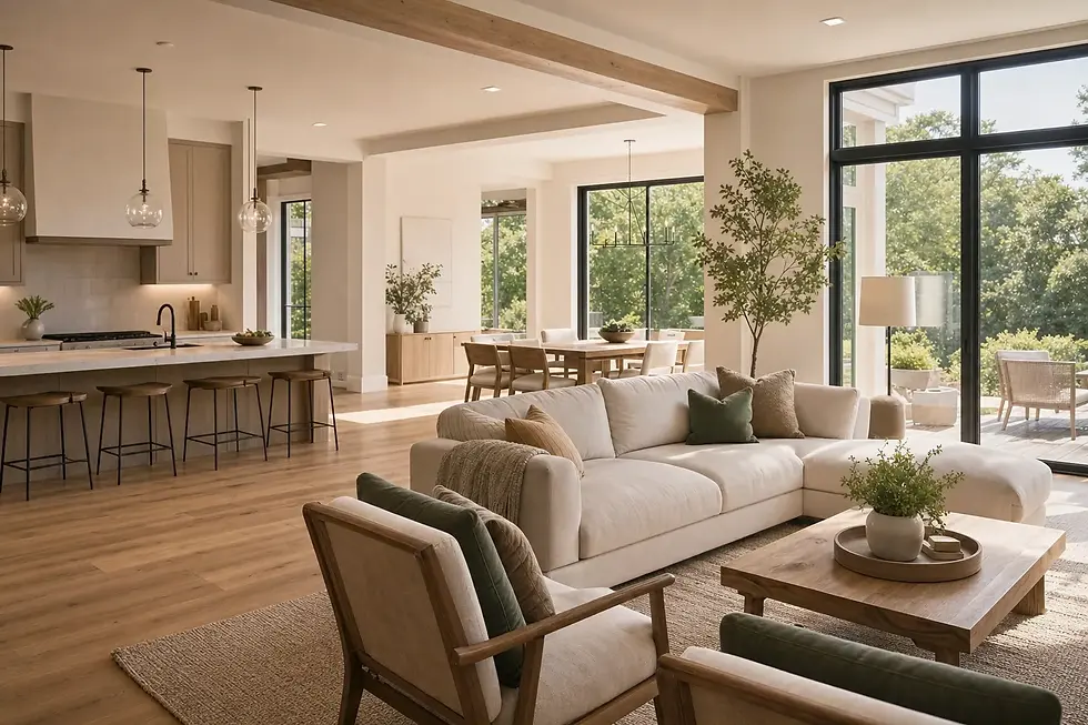
Among the more modern types of architectural drawings, 3D renderings and visualizations bridge the gap between abstract plans and tangible reality. These are computer-generated images that provide realistic or conceptual views of an architectural design. Ranging from simple massing studies to photorealistic scenes complete with materials, shadows, and environmental context, they allow anyone to see what a building will truly look like before a single brick is laid.
These visualizations are powerful communication tools that bring a design to life. While traditional 2D drawings like floor plans and elevations are essential for construction, 3D renderings convey the aesthetic, atmosphere, and spatial experience of a home. Firms like Zaha Hadid Architects and Bjarke Ingels Group have popularized their use to showcase fluid, futuristic concepts and help clients, stakeholders, and design teams fully grasp a project's visual impact.
Purpose and Implementation
The primary purpose of a 3D rendering is to create an emotional connection and clear understanding of the proposed design. For a new custom home, these visualizations are used to:
Make Informed Decisions: Homeowners can see how material choices, paint colors, and lighting will look together, preventing costly changes during construction.
Market the Property: Real estate developers use photorealistic renderings for marketing materials, allowing them to sell properties before they are even built.
Secure Approvals: Presenting a realistic visualization to a design review board or homeowners' association can help communicate the design intent more effectively than 2D drawings alone.
As this video demonstrates, the process of creating a rendering transforms technical data into an immersive and compelling visual narrative, making complex designs accessible to everyone.
Best Practices for 3D Renderings
To create effective and convincing visualizations, a thoughtful approach is required.
Pro Tip: Don't just show the building in isolation. Including people, landscaping, and cars not only provides a sense of scale but also helps tell a story about how the home will be lived in and experienced.
Key considerations include starting with simple massing studies to establish the overall form before investing time in detailed materials. Using realistic lighting conditions, such as simulating the sun's path at different times of day, adds authenticity. Finally, creating multiple views that showcase both sweeping exterior perspectives and intimate interior moments provides a comprehensive understanding of the entire project.
7. Reflected Ceiling Plans
Among the many types of architectural drawings, the Reflected Ceiling Plan (RCP) offers a unique and critical perspective. This drawing presents a top-down view of the ceiling as if you were looking into a giant mirror placed on the floor, hence the term "reflected." This inverted viewpoint allows for a clear illustration of all objects located on the ceiling's surface.
RCPs are crucial for coordinating the various systems that are housed within or mounted on the ceiling. They show the precise location of lighting fixtures, HVAC vents, smoke detectors, sprinkler heads, and any architectural details like coffers or exposed beams. Without an RCP, integrating these essential mechanical, electrical, and plumbing (MEP) elements with the aesthetic design would be a chaotic and inefficient process.
Purpose and Implementation
The primary purpose of a Reflected Ceiling Plan is to provide a comprehensive, coordinated map of all ceiling-mounted elements. For a new custom home, this drawing is used to:
Integrate Systems: It ensures that lighting, mechanical systems, and fire safety equipment are placed logically and do not conflict with each other or structural components.
Finalize Lighting Design: Homeowners and designers use the RCP to visualize the lighting scheme, ensuring proper illumination and ambiance in every room.
Guide Tradespeople: Electricians, HVAC technicians, and other subcontractors rely on the RCP for the exact installation locations of fixtures and diffusers.
This quick reference summary highlights the essential components and benefits of a well-drafted Reflected Ceiling Plan. It is a key tool for transforming a ceiling from a simple overhead plane into a functional and beautifully designed surface.
Best Practices for Reflected Ceiling Plans
To ensure a successful and conflict-free installation, Reflected Ceiling Plans require meticulous detail and coordination.
Pro Tip: When reviewing an RCP, cross-reference it with the electrical plan and the furniture layout on the floor plan. This ensures that light fixtures are centered over key areas like a dining table or kitchen island, and that switches are logically placed for how you will use the room.
Key considerations include clearly indicating all ceiling heights and transitions, such as soffits or vaulted areas. It's vital to use a legend with standard symbols to identify every fixture type, from recessed cans to pendant lights and ceiling fans. Finally, coordinating directly with MEP engineers before finalizing the plan prevents costly on-site conflicts and ensures all systems work together harmoniously.
7 Types of Architectural Drawings Compared
Drawing Type | Implementation Complexity | Resource Requirements | Expected Outcomes | Ideal Use Cases | Key Advantages |
|---|---|---|---|---|---|
Floor Plans | Moderate | CAD/BIM software, architectural knowledge | Clear spatial layout, circulation, permit docs | Residential, offices, hospitals, restaurants | Easy to understand, essential for planning and permits |
Elevations | Moderate | CAD/BIM software, design coordination | Exterior/interior facade representation | Facade design, material specification, zoning | Communicates design intent & aesthetics clearly |
Sections | Moderate to High | CAD/BIM software, structural knowledge | Vertical spatial relationships, structural insight | Multi-story buildings, structural coordination | Reveals vertical connections and accessibility |
Site Plans | High | Survey data, CAD software, multi-disciplinary input | Building context, site layout, zoning compliance | Large projects, campus planning, subdivisions | Ensures zoning compliance and site integration |
Construction Details | High | Specialized knowledge, detailed drafting | Precise assembly and installation instructions | Complex assemblies, warranty compliance | Reduces construction errors, ensures performance |
3D Renderings and Visualizations | High | Advanced 3D software, artistic skill | Realistic designs, client presentations | Marketing, client approvals, design reviews | Excellent communication, early issue detection |
Reflected Ceiling Plans | Moderate | Coordination with MEP disciplines, CAD software | Ceiling layout, MEP coordination | Commercial buildings, hospitals, retail spaces | Prevents system conflicts, ensures code compliance |
Bringing Your Vision to Life with the Right Plans
Navigating the journey of building a new home is a complex but incredibly rewarding process. As we have explored, the various types of architectural drawings are not just technical documents for builders; they are the language that translates your vision into a tangible, livable reality. Each drawing type offers a unique perspective, working in concert to create a complete and unambiguous instruction set for your project.
From the foundational layout of floor plans to the exterior aesthetics defined by elevations, and the structural integrity revealed in section drawings, every document plays a pivotal role. The site plan situates your home within its environment, while construction details ensure that even the smallest connections are executed with precision. Meanwhile, 3D renderings provide the crucial emotional and visual connection, allowing you to experience the space long before the first foundation is poured. Understanding this complete set is your most powerful tool.
From Blueprint to Reality: Your Role in the Process
Your ability to read and interpret these plans empowers you to be an active participant rather than a passive observer. It allows you to ask targeted questions, provide specific feedback, and make informed decisions that align with both your budget and your aspirations. When you can confidently discuss the difference between an elevation view and a section cut, you build a stronger, more collaborative relationship with your architect, designer, and construction team.
This knowledge transforms the entire building experience. It minimizes misunderstandings, reduces the likelihood of costly errors, and ultimately ensures the final structure is a true reflection of the home you envisioned. Think of these drawings as the comprehensive script for your home's story. By learning to read them, you become a co-author, ensuring the narrative unfolds exactly as you intended.
Key Takeaways for Your Project Success
To maximize the value of your architectural plans, remember these core principles:
Holistic Understanding: No single drawing tells the whole story. Always cross-reference between plans, sections, and elevations to see how different elements interact.
Question Everything: If a detail on the floor plan seems unclear, or if an elevation doesn't match your expectations, speak up immediately. It is far easier and cheaper to adjust a line on a drawing than to move a wall during construction.
Details Matter: Pay close attention to the construction detail sheets. These drawings dictate the quality, durability, and performance of your home, from window flashing to foundation connections.
Embrace Visualization: Use 3D renderings and reflected ceiling plans to fully grasp the feel and flow of the space. This helps you make better decisions about lighting, materials, and spatial relationships that 2D drawings alone cannot convey.
Mastering these types of architectural drawings is the final, crucial step in turning a dream into a detailed, actionable plan. It is the bridge between imagination and execution, ensuring your future home is built with clarity, precision, and a shared understanding of the final goal.
Ready to start your journey with a complete and professionally designed set of plans? At RBA Home Plans, our award-winning designs include every drawing type discussed here, providing you and your builder with the clear, comprehensive documentation needed for a successful build. Explore our extensive catalog of customizable home plans at RBA Home Plans and find the perfect blueprint for your future home today.
Comments